| |
| |
- Description
Features
- Benefits
- Optional Software
| |
| The SmartSensor is an Embedded Microcontroller device
designed to collect and monitor welding parameters. In its basic form the SmartSensor is configured to monitor welding current and provides two user 24 VDC inputs and 24 VDC outputs. It also provides a RS-485 serial port with the Modbus™ protocol to allow the user to access the run time data and enable control functions. Additional sensors can be added to monitor other welding
parameters. The SmartSensor can monitor Voltage, Wire Speed, Travel Speed, Gas Flow or Temperature. |
| The SmartSensor can be used for the following monitoring functions: |
 |
Arc On Time |
|
Weld Counter |
|
Average Current and Arc On Time |
|
Record Average Volt, Amp, Wire Speed, Gas Flow or Temperature and Travel Speed (requires additional sensors) |
|
With user supplied inputs and optional sensors, the control can provide PASS/FAIL testing for each completed weld based on a four-part mapped learn cycle and user defined Sigma values |
|
Sensor can provide two levels of PASS/FAIL testing: |
| |
|
Weld Pass/Fail |
|
Part Pass/Fail |
|
|
Total isolation of all sensors from the welding arc. Arc current is measured using a laser trimmed
hall-effect transducer. Arc voltage sensor provides a 1 KV isolation using capacitive isolation technology. |
| The unit provides weld current detection and can be used as an arc active sensor. It also provides an accumulative arc on timer and will accumulate the weld current during a weld cycle. At the end of the weld cycle the average weld current and arc on time is stored in Non-Volatile memory. The SmartSensor has onboard memory to store up to 1040 weld summary data records. |
| The sensor can also provide Arc Voltage data acquisition and monitoring, and with individually purchased sensors provide Wire Speed, Travel Speed, and Gas Flow or Temperature data acquisition and monitoring. |
|
| |
|
Hall-effect current transducer with 25 mm opening for
welding cable |
|
A screw terminal block connections for positive and negative voltage sense leads |
|
The unit provides weld current detection and can be used as an arc active sensor |
|
There are two 24 VDC inputs and two 24 VDC SSR outputs |
|
The sensor can be configured to store up to 1040 weld summaries in internal NVRAM. The Date/Time stamped summaries may then be downloaded via
the Modbus Port |
|
| |
|
Provides electrical isolation and reduces cable heating by eliminating additional mechanical connections |
|
Provides easy installation of voltage sense leads
and allows custom wire length |
|
Communication with multiple SmartSensors
devices with optional software package |
|
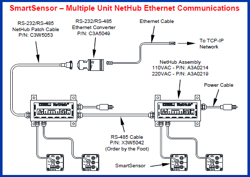
The sensor can also be used with an Ethernet port and provide Modbus over Ethernet connectivity which will allow multiple users to connect to multiple sensors via an Ethernet connection |
| |
|
|
| |
| |
| The optional ArcTrack II program is designed to use the various CWT Weld data sensors and provides advance data logging function. It is designed to provide a simple GUI interface for weld data logging for manual weld procedure development and documentation. It provides a Sweep chart option to graphically monitor and collect welding data from remote CWT Sensors. It provides both run time and summary data files that can be directly imported into Microsoft Excel for further evaluation. This program can be used with the following CWT sensors; Micro ADM, Intella-DART, WireTrak, Smart Sensor, GFM and the WDL-3. The sensor provides fault testing of the basic welding parameters (i.e. Volts, Amps, Wire Speed, Gas Pressure and Arc Time). It incorporates an advanced testing algorithm that provides three levels of fault testing. The sensor provides in-process parameter limit testing, Arc Density (AAD) for each weld in a Part and an ADD, Weld Count and Volume Applied test for each Part. The sensor also features a Part Learn Mode that allows the sensor to establish statistical control limits based on actual production parts. The ArcTrack II program allows the user to upload run time weld data and stored SPC weld summary data. |
|
 |
|
|
|
| |
Product Specifications |
|
- Sensor Limits
- General Specifications
| |
| Arc Current |
|
| ±2.0% of full scale ±2 digits |
| ±2.5% of full scale ±3 digits |
|
| Arc Voltage |
|
| ±1.5% of full scale ±2 digits |
| ±2.0% of full scale ±2 digits |
|
| Wire Feed Speed |
10 – 1000 ipm (4.2 – 423 mm/s) |
±3% of full scale ±2 digits |
| Travel Speed |
1.0 – 100.0 ipm (0.4 – 42 mm/s) |
±3% of full scale ±2 digits |
| Analog Inputs |
0 – 5.0 vdc |
±1.5% of full scale ±2 digits |
| Digital Inputs |
10 – 28 vdc @ 5 ma |
|
| Digital Outputs |
| 12 – 26 vdc @ 100 ma |
| (depends on voltage input) |
|
|
| Welds/Part |
1 – 200 Welds/Part |
|
| Weld Memory |
1040 Welds summaries stored in NVRAM |
|
| Weld Testing* |
Pass/Fail per Weld based on Volume, AAD and Work applied |
|
| Part Testing* |
Pass/Fail per Part based on Weld Count, Total Volume, Total AAD and Total Work Applied |
|
| * Testing requires volt, amp and wire speed sensor for calculations of volume and work applied. |
|
| |
| Dimensions |
| 2.1”H x 2.5”W x 5.6”L (53mm x 64mm x 143mm) |
| Note: Allow an additional clearance of 1.5” (38mm) below sensor for connector clearance. Max welding cable size 1” (25 mm) |
|
| Weight |
7 oz (0.198 kg) |
| Communications |
MODBUST RTU |
| Power Requirements |
12 – 26 Vdc @ 100ma |
| System Interface |
2 – 24 vdc inputs, 2 vdc SSR outputs |
|
|
|
| |
Communications |
|
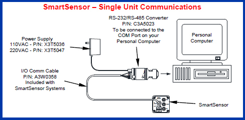
- Single Unit
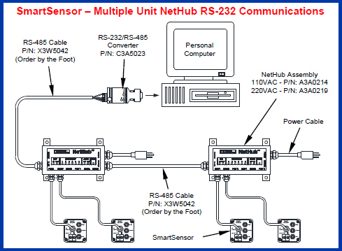
- Multiple Unit with RS-232 Communications
- Multiple Units with Etnernet Communications
|
|
| |
|
|
 |
|
|
| Please disable browser pop-up blockers for documents on cweldtech.com to allow PDF files. |
|
 |
| Note - All documents are in an Adobe PDF file format. |
|
 |
| Press to enter download area for Autocad DXF drawing format. |
|
|