| |
| |
- Description
- Features
- Benefits
- Parameter Monitored/Logged
- Modes of Operation
- Software
| |
The Weld Data Logger represents leading edge technology in arc welding data collection and logging. The micro-controller based weld data acquisition system provides a means of measuring and documenting all basic welding parameters when used with external serial printer or PC.
The WDL-3 can store uo to 4000 weld summeries in non-volatile memory. Additionally the WDL-3 has the unique ability to calculate heat input using the optional travel speed transducer, a user specified Travel Speed or the actual weld length and accumulated arc time. An Ethernet port is available for remote data collection and stored weld summary data upload.
There are two different Systems Configurations for the WDL-3.
Ethernet System - P/N: A0A0171-ETH
(Enclosure contains built-in auto-sensing 10/100 Mbps Ethernet port)
USB System - P/N: A0A0171-USB
(Enclosure contains built-in USB port) |
| |
 |
Data Logging: Welding parameter data can be dumped to an external printer for hard copy printout and fault analysis or to a PC using ArcTrack II software for data storage and analysis. |
 |
Mean and standard deviation for each parameter |
 |
Graphic analysis for single and multiple weld data files |
| |
|
|
| |
The optional ArcTrack II program is designed to use the various CWT Weld data sensors and provides advance data logging function. It is designed to provide a simple GUI interface for weld data logging for manual weld procedure development and documentation. It provides a Sweep chart option to graphically monitor and collect welding data from remote CWT Sensors. It provides both run time and summary data files that can be directly imported into Microsoft Excel for further evaluation. This program can be used with the following CWT sensors; Micro ADM, Intella-DART, WireTrak, Smart Sensor, GFM and the WDL-3.
The sensor provides fault testing of the basic welding
parameters (i.e. Volts, Amps, Wire Speed, Gas Pressure and Arc Time).
It incorporates an advanced testing algorithm that provides three
levels of fault testing. The sensor provides in-process parameter
limit testing, Arc Density (AAD) for each weld in a Part and an ADD,
Weld Count and Volume Applied test for each Part. The sensor also features a Part Learn Mode that allows the sensor
to establish statistical control limits based on actual production
parts. The ArcTrack II™ program allows the user to upload
run time weld data and stored SPC weld summary data.

|
|
|
| |
| |
System Configurations |
|
- WDL III Ethernet System
- WDL III USB System
| |
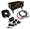 |
| WDL-3 Ethernet System |
| P/N: A0A0171-ETH |
| |
| System Includes: |
| WDL-3 Enclosure with built-in auto-sensing 10/100 Mbps Ethernet port |
| Current Sensor woth 6 meter cable |
| Voltage Sensor with 6 meter cable |
|
|
| |
 |
| WDL-3 USB System |
| P/N: A0A0171-USB |
| |
| System Includes: |
| WDL-3 Enclosure with built-in USB port |
| Current Sensor with 6 meter cable |
| Voltage Sensor with 6 meter cable |
|
|
|
|
| |
|
| |
System Options |
|
- Wire Speed Sensor
- Travel Speed Sensor
- Gas Flow Monitor
- Temperature Sensor
- Printer
- Software
| |
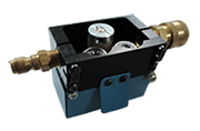 |
| Wire Speed Sensor Kits |
| Up to 1/16” Diameter Wire - P/N: A0A0179 |
| 1/16” to 3/16" Diameter Wire - P/N: A0A0180 |
| |
| Kits includes sensor and 6 meter cable |
| |
10-1000 IPM (4.2 - 423mm/s) +/- 3%,
1 IPM (0.4mm/s) Resolution |
|
|
| |
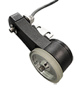 |
| Travel Speed Sensor Kit |
| P/N: A0A0182 |
| |
| Kit includes sensor, bracket and 6 meter cable |
| |
1-100 IPM (0.42 - 42mm/s) +/- 3%,
0.1 IPM (0.04mm/s) Resolution |
|
|
| |
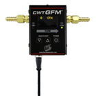 |
| Gas Flow Monitor Kit |
| P/N: A0A0183 |
| |
| Kit includes monitor, bracket, fittings and 6 meter cable |
| |
5-255 SCFH (2-120 LPM) +/- 2% of full scale +/- 1 digit,
1 SCFH (1 LPM) Resolution,
50 PSIA (344 KPA) Maximum Operation Pressure |
|
|
| |
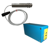 |
| Thermocouple "K" Sensor Kit - P/N: A0A0184 |
| Thermocouple "J" Sensor Kit - P/N: A0A0185 |
| Thermocouple "T" Sensor Kit - P/N: A0A0186 |
Infrared Sensor Kit - P/N: A0A0187
0 – 1000°F (-18° - 538°C)
|
| |
| Kits includes sensor and 6 meter cable |
|
|
| |
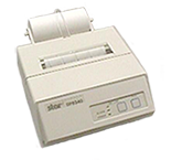 |
| Serial Printer Kit |
| P/N: A0A0188 |
| |
| Kit includes printer and cable |
| |
|
|
| |
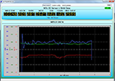 |
| ArcTrack II Software |
| P/N: A5Z0051 |
| |
| It provides weld data collection routines that allow the user
to collect run-time weld data and store this data for future analysis.
The program also provides a Graphical and statistical program
to display and analysis stored weld data files. The ArcTrack II™
program is designed for use with Windows® XP Service Pack 2 orlater platforms. |
|
|
|
|
| |
|
| |
Product Specifications |
|
- Sensor Limits
- Mechanical
- Electrical
| |
| Arc Voltage |
0-80 Volts DC +/- 1%, 0.1 Volt Resolution |
| Arc Current |
0-1000 Amps DC +/- 1%, 1 Amp Resolution |
| Travel Speed |
1-100 IPM (0.42 - 42mm/s) +/- 3%,
0.1 IPM (0.04mm/s) Resolution |
| Wire Speed |
10-1000 IPM (4.2 - 423mm/s) +/- 3%,
1 IPM (0.4mm/s) Resolution |
| Gas Flow |
5-255 SCFH (2-120 LPM) +/- 2% of full scale +/- 1 digit,
1 SCFH (1 LPM) Resolution,
50 PSIA (344 KPA) Maximum Operation Pressure |
| Temperature |
Range, Resolution and Accuracy Depend on Sensor Used. Consult Factory for Options. |
|
| |
| Dimensions |
7.50" W x 4.50" L x 2.50" L (51 mm X 165mm X 280mm) |
| Weight |
4 lbs. (1.8kg) |
|
| |
| Power Requirements |
12 - 32 vdc @ 0.5 amps |
| Communications |
Ethernet or USB, and Serial Printer Interface |
|
|
|
| |
|
|
 |
|
|
| Please disable browser pop-up blockers for documents on cweldtech.com to allow PDF files. |
|
 |
| Note - All documents are in an Adobe PDF file format. |
|
 |
| Press to enter download area for Autocad DXF drawing format. |
|
|